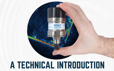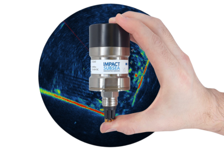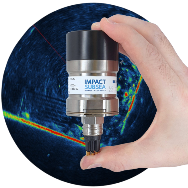
The ISS360 & ISS360HD are compact imaging sonars widely used on underwater Remotely Operated and Autonomous Vehicles. These two sonars are also used in numerous stand-alone applications such as search and recovery.
Sonar Image Quality
A core consideration of any imaging sonar is the quality of the imagery.
For those already familiar with sonar terminology, the ISS360 provides a 2.2° angular resolution (at 700kHz) coupled with a 2.5mm range resolution and a distance measurement range of up to 90 meters/295 feet.
The ISS360HD provides a 1° angular resolution (at 700kHz) a range resolution of 2.5mm and a distance measurement range of up to 100 meters/328 feet.
To provide further detail of how Range and Angular Resolution influence the image quality:
Range Resolution
Range Resolution is the ability to distinguish between targets based on distance away from the sonar. The lower this value the higher the resolution of the image.
Range Resolution is a particularly important factor to consider when working at shorter distances, as it will make a significant difference to the resolution of imagery you see on screen. At greater distance, small details are missed due to the compression of the imagery on the computer display – so range resolution becomes a less critical factor for general imaging sonar use.
For operation at lower ranges, the ISS360/ISS360HD utilises a CHIRP (Compressed High Intensity Radar Pulse) from 600 to 900kHz. Range resolution of a CHIRP sonar system is equal to the velocity of sound/(bandwidth x 2). This enables a 2.5mm range resolution to be obtained in the ISS360 sonar.
For reference, a 200kHz bandwidth CHIRP would typically provide a 3.75mm range resolution and a 100kHz bandwidth CHIRP would provide a 7.5mm range resolution.
If you consider a non-CHIRP sonar system which operates by transmitting single frequency pulses, the pulse length dictates range resolution. In a single frequency sonar system Range Resolution is equal to (pulse length x velocity of sound) / 2. For example a 200μs single frequency pulse will give around a 150mm range resolution, assuming a speed of sound of 1,500 meters per second.
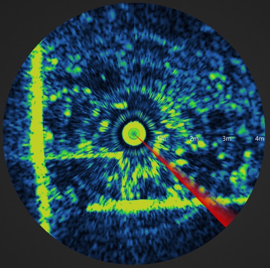
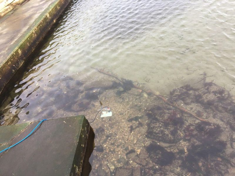
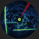
The images below are examples of how range resolution at short ranges compares. The image on the left is a single frequency 200μs pulse (150mm range resolution) and the image on the right is a CHIRP 200μs pulse with 100kHz bandwidth (7.5mm range resolution):
Angular Resolution
Angular Resolution is the ability to distinguish two targets which are at the same physical range away from the sonar (sitting side by side). This is defined by the horizontal acoustic beamwidth of the sonar.
Angular resolution typically becomes more important as distance increases. At longer distances the footprint of the acoustic beam will become one of the most influential factors in defining the image clarity.
The ISS360 has an angular resolution of 2.2° which is ideal for many applications. The ISS360HD has an angular resolution of 1° which provides exceptional image quality.
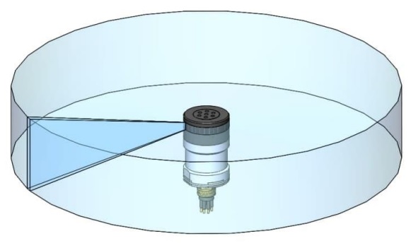
The illustration below shows the acoustic beam from the ISS360. This is then stepped 360° around the sonar to provide the full sonar plot.
IS3 Acoustics
In addition to CHIRP acoustic signalling the ISS360 & ISS360HD imaging sonars also benefit from the Impact Subsea Signalling Scheme (IS3).
IS3 uses advanced phase modulation and coding techniques to provide exceptional signal integrity, timing accuracy and range resolution. This scheme can be enabled or disabled within the sonar settings. When enabled, IS3 is used in conjunction with the standard sonar acoustic settings (alongside CHIRP at shorter ranges and single frequencies at longer ranges).
In addition to increasing range resolution, IS3 reduces the interference between multiple ISS360 Imaging Sonars operating in close proximity. This can be highly useful if multiple imaging sonars are in use on the same AUV or ROV.
Other Factors
Range Resolution and Angular Resolution are two of the main parameters used to define sonar image quality. However there are other factors which come into play.
The acoustic detection method in use can make a large difference to the overall image quality, in terms of image noise level and range capability. The ISS360 & ISS360HD use a digital correlation technique to detect the returning acoustic pulses. The two sonars do not employ any filtering of the incoming data. All incoming data is processed directly through the digital correlator to ensure no loss of quality. The complete digital process without degradation of the incoming data is the reason the ISS360 sonar imagery often looks ‘cleaner’ than some alternative sonars of a comparable angular resolution.
There are also other elements affecting the displayed image, the quality of the electronic analogue front end design, transmit power, CHIRP implementation, detection algorithm, transducer design etc which will be unique to each sonar manufacturer.
The technical specification of a sonar system will provide a reasonable appreciation of what to expect from a sonar in terms of its capability. To take all possible factors into account however, study of the actual sonar imagery produced should be undertaken.
Example imagery from the ISS360 & ISS360HD range of sonars can be found on the ISS360 page here.
Scanning Speed
In a perfect mechanically scanning sonar, scanning speed should only be limited by the travel time of the acoustic pulse (journey from sonar to maximum range and back again).
The ISS360 & ISS360HD Sonars comes very close to this theoretical maximum scanning speed. This is achieved through two factors:
Ethernet Comms
In addition to Serial communications capabilities, RS232 and RS485, the ISS360 & ISS360HD also come with Ethernet communications capability as standard. This provides a high bandwidth communications channel which does not restrict the scanning speed of the sonar.
Processing Power
An advanced digital correlation technique is employed to detect the returning acoustic waveform. This correlator is run exceptionally fast utilising the ISS360/ISS360HD’s powerful internal processor.
The high processing speed of the ISS360/ISS360HD’s hardware combined with the unrestricted communications path enables a very fast scanning speed. This is particularly noticeable at lower ranges where processing power is critical.
In third party benchmark testing against other popular scanning sonars in the market, the ISS360 was found to scan up to six times faster at shorter ranges.
For those using the sonar for the purpose of obstacle avoidance operations, this is a significant step forward from what was previously available. For many applications the increased scanning speed negates the requirement to utilise a multibeam sonar for obstacle avoidance purposes.
The video below shows the scanning speed of the ISS360 Sonar when operating over Ethernet communications. Low to high scanning resolutions are shown:
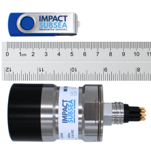
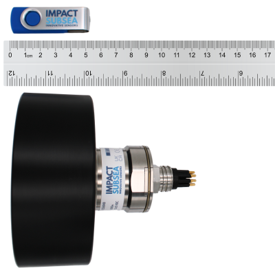
Size & Weight
The ISS360 was developed to be the most compact, mechanically scanned imaging sonar in the world.
Highly compact with a weight of 0.37kg/0.82lbs in air ensures that the ISS360 is exceptionally easy to integrate onto all underwater vehicles – from observation to work class. The ISS360HD is slightly heavier at 0.76kg/1.675lbs in air.
Due to the use of the latest electronics and advanced digital acoustic engine, the compact sonar size has not compromised performance. With the highly compact ISS360 and ISS360HD outperforming sonars which are many times its size.
Reliability
The ISS360/ISS360HD benefits from an inductively coupled transducer. This means there are no slip rings within the sonar so there are no components to wear out and require periodic replacement.
The body is titanium, which provides an extremely robust and long lasting housing. The use of titanium instead of anodised aluminium ensures that the housing will not need to be periodically replaced.
The ISS360/ISS360HD also benefits from a fused comms lines, undervoltage protection and reverse voltage protection.
The above features enable a sonar which is very long lasting and highly resilient in tough environments.
Software
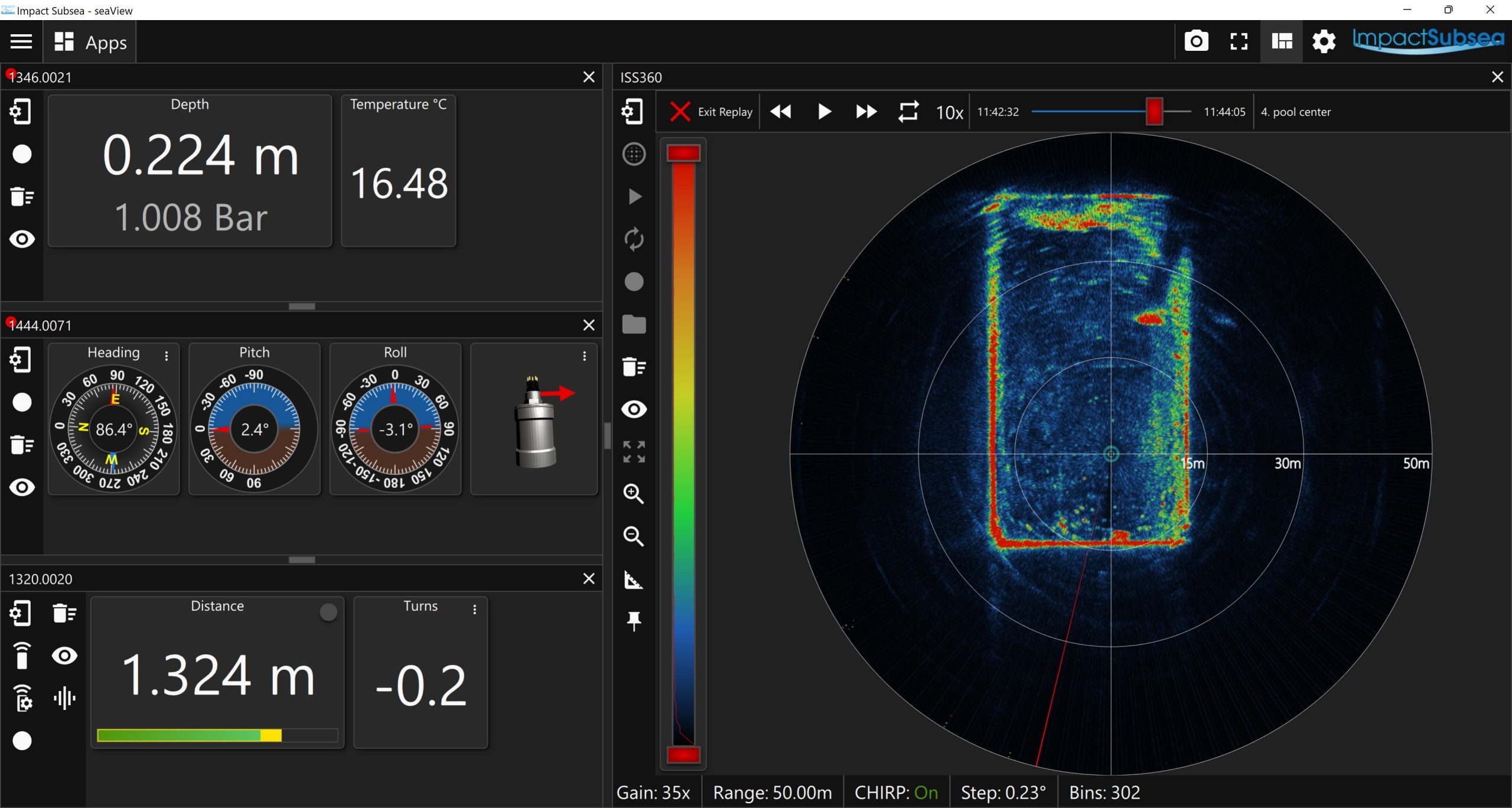
The ISS360/ISS360HD operates with the Impact Subsea seaView V3 software, allowing seamless use alongside the Impact Subsea Altimeter, Depth Sensor, AHRS sensor, Profiling Sonars and FMD System.
A full overview of the ISS360/ISS360HD Sonar application within the seaView V3 software can be viewed below:
For those wishing to use the ISS360/ISS360HD with an autonomous underwater vehicle, a Software Development Kit (SDK) is freely available to allow direct integration of the sonar. The SDK can be accessed on Github here. There is also an example project here.
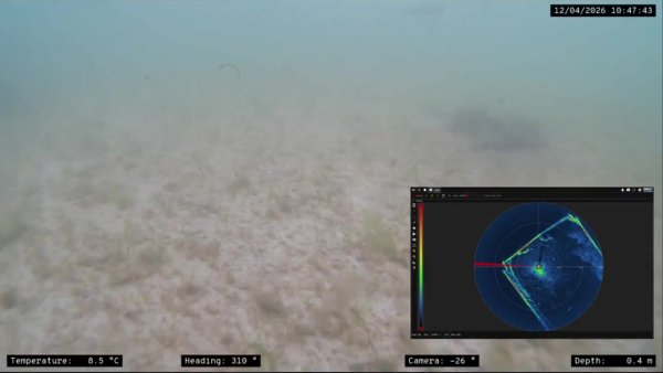
Shown below is a seaView software screen, displaying the ISS360 Sonar operating alongside the Impact Subsea Depth Sensor, Altimeter and AHRS sensor:
Attitude Reference System
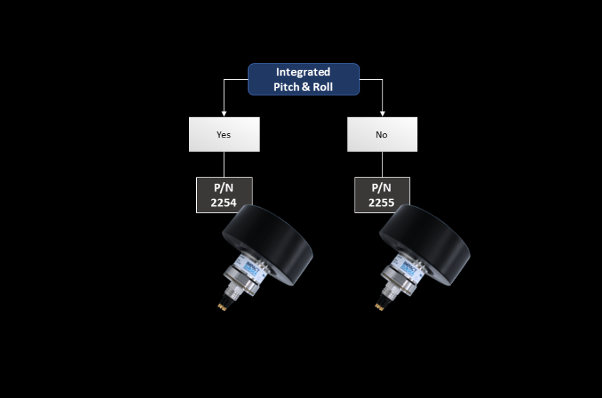
The ISS360/ISS360HD is optionally available with an in-built Attitude Reference System (ARS). This provides Pitch and Roll as a viewable output.
Aside from a useful additional measurement parameter, the ARS can also be used to ensure that the ISS360/ISS360HD is perfectly level during standalone operation. This will ensure that the maximum range is achieved in all directions around the sonar.
Physical Configuration
To ensure the ISS360/ISS360 is simple to integrate into any Autonomous Surface Vehicle (ASV), Autonomous Underwater Vehicle (AUV) or Remotely Operated Vehicle (ROV) the ISS360 is available in two configurations:
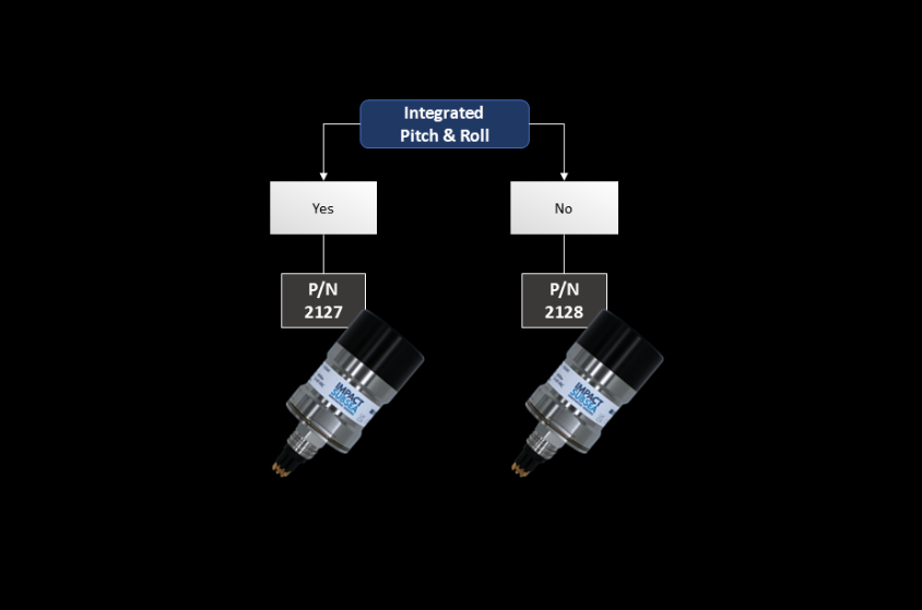
The ISS360HD is also available in two configurations:
Overall
The ISS360/ISS360HD series of imaging sonars provide excellent image quality and fast scanning speed. Presented in a compact and robust form factor makes the ISS360/ISS360HD ideal for a multitude of underwater applications.
If you would like to discuss the ISS360/ISS360HD in more detail, and how it can be used in your underwater application, please drop us an email at sales@impactsubsea.co.uk
Or alternatively, call us on +44 1224 460 850
The latest ISS360/ISS360HD Imaging Sonar datasheet, manual, 3D models and further technical information can be found on the product page
Watch and learn more about the ISS360/ISS360HD Imaging Sonar: YouTube playlist